Installation of steel wire rope
Learn more about installation of your steel wire rope

Certain conditions, especially in offshore activities or when lifting persons or potentially dangerous loads such as molten metals, corrosive materials, or fissile materials, pose significant hazards. In such instances, a competent person should assess the degree of risk, and the working load limit should be adjusted accordingly.
General: Steel wire rope slings are often more cost-effective and easier to use than chain slings. Galvanized wire rope provides effective corrosion protection, while in extreme environments, stainless wire ropes may be preferred. For heavy lifting, wire rope slings are generally the optimal choice.
Material/Design: Wire rope slings should be manufactured using rope grades of either 1770 or 1960 N/mm². In multi-leg slings, the rope dimension and grade should be consistent for each leg. The working load limit of the lower terminal fitting(s) should be at least equal to that of the leg(s) to which it is fitted. For 3- and 4-leg slings, a master link with an intermediate link should be used.
Safety Factor: 5:1
Standard: EN 13414-1
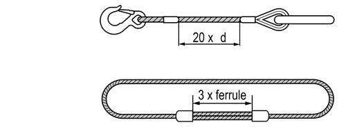
The minimum length of plain rope between the inside ends of ferrules terminating a sling leg should be 20 times the nominal rope diameter. For splices, the minimum length of plain rope between the tails should be at least 15 times the nominal rope diameter. In endless slings, the length between the ferrules should not be less than three times the length of the ferrule after pressing.
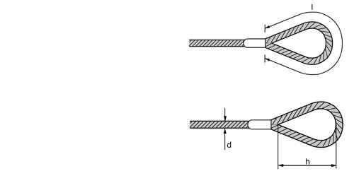
The peripheral length (l) of a soft eye should be at least four rope lay lengths. CERTEX applies the standard that the length (h) of the soft eye should be at least 15 times the rope diameter (d).
The working load limit of any master link should be at least equal to that of the sling. The working load limit of any intermediate link fitted to a three-leg or four-leg sling should be at least equal to 1.6 times the WLL of one of the legs suspended from it.

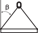
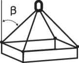
WARNING! When using a steel wire rope sling for projected lifting with an angle (ß) less than 45°, the working load limit will increase. This information should be communicated at the time of the order.
Single leg and endless slings: The measured length of a ferrule-secured sling should not differ from the nominal length by more than two rope diameters or 1% of the nominal length, whichever is greater.
The measured length of a spliced sling should not differ from the nominal length by more than four rope diameters or 2% of the nominal length, whichever is greater.
Where single leg slings are intended to be used as matched sets, the difference in length of matched sets of ferrule-secured eye slings should not exceed the rope diameter or 0.5% of the nominal length, whichever is greater.
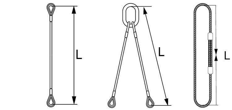
Multi-leg slings: The measured individual leg length of a ferrule-secured sling should not differ from the nominal length of the sling by more than two rope diameters or 1% of the nominal length, whichever is greater.
The difference in length between the individual legs of any multi-leg sling under no load should not exceed 1.5 times the rope diameter or 0.5% of the nominal length, whichever is greater.
"Laid" (cable-laid) endless slings: The measured length for cable-laid grommets should have a tolerance of ±1d or 1% of the nominal length, whichever is greater, for grommets with a diameter <61 mm. For grommets with a diameter >65 mm, the tolerance should be ±0.5d or 0.5% of the nominal length, whichever is greater.
Each sling should be provided with a marking plate or marked in the ferrules (single leg and endless slings) with the manufacturer's identifying mark, working load limit (WLL), length, manufacturing date, and CE marking.
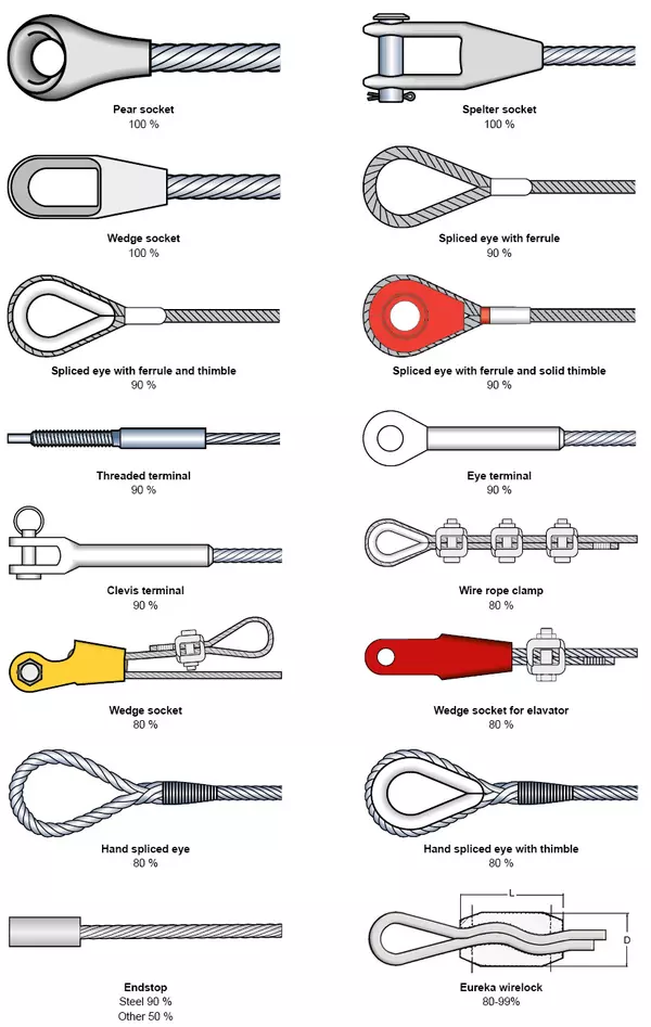
The most commonly used rope fittings should be indicated with the remaining percentage of the steel wire's minimum breaking force.
Working Load Limit (WLL) for Steel Wire Rope Sling
| Single leg sling: | |
| WLL ton | (Fmin x KT) (Zp x g) |
| Endless sling (choke): | |
| WLL ton | (Fmin x KT x 2 x 0.8) (Zp x g) |
| Multi-leg sling: | |
| WLL ton | (Fmin x KT x KL) (Zp x g) |
Where:
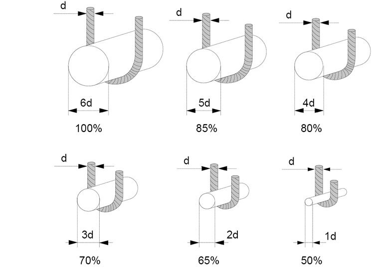
CERTEX recommends considering that the slings' capacity will be lower when the bending diameter decreases. For example, if the rope bends around a bearing point with the same diameter as the rope itself, the capacity will decrease to half, as illustrated in the figure.
| Single | 2-leg sling* | 3- and 4-leg sling* | Endless | |||||||
 |
 |
 |
 |
 |
 |
 |
 |
|||
| Angle of inclination | 1-leg | Laced | U-lift | 0°- 45° | 45° - 60° | 0°- 45° | 45° - 60° | 1-leg | Laced | U-lift |
| Load factor | 1 | 0,8 | 2 | 1,4 | 1 | 2,1 | 1,5 | 2 | 1,6 | 4 |
| mm | WLL ton | |||||||||
| 8 | 0,75 | 0,6 | 1,5 | 1,1 | 0,75 | 1,6 | 1,1 | 1,4 | 1,2 | 3 |
| 9 | 0,9 | 0,8 | 1,8 | 1,26 | 0,9 | 2 | 1,4 | 1,8 | 1,5 | 3,6 |
| 10 | 1,2 | 0,95 | 2,4 | 1,7 | 1,2 | 2,5 | 1,8 | 2,4 | 1,9 | 4,8 |
| 11 | 1,4 | 1,1 | 2,8 | 2 | 1,4 | 3 | 2,2 | 2,8 | 2,3 | 5,6 |
| 12 | 1,7 | 1,3 | 3,4 | 2,4 | 1,7 | 3,6 | 2,6 | 3,4 | 2,7 | 6,8 |
| 13 | 2 | 1,6 | 4 | 2,8 | 2 | 4,2 | 3 | 4 | 3,2 | 8 |
| 14 | 2,3 | 1,8 | 4,6 | 3,2 | 2,3 | 4,8 | 3,5 | 4,6 | 3,7 | 9,2 |
| 16 | 3 | 2,4 | 6 | 4,2 | 3 | 6,3 | 4,5 | 6 | 4,8 | 12 |
| 18 | 3,8 | 3,1 | 7,6 | 5,3 | 3,8 | 8 | 5,7 | 7,6 | 6,1 | 15,2 |
| 20 | 4,7 | 3,8 | 9,4 | 6,6 | 4,7 | 10 | 7,1 | 9,4 | 7,6 | 18,8 |
| 22 | 5,7 | 4,6 | 11,4 | 8 | 5,7 | 12 | 8,5 | 11,4 | 9,2 | 23 |
| 24 | 6,8 | 5,4 | 13,6 | 9,5 | 6,8 | 14,3 | 10,2 | 13,6 | 11 | 27 |
| 26 | 8 | 6,4 | 16 | 11,2 | 8 | 16,8 | 12 | 16 | 12,8 | 32 |
| 28 | 9,3 | 7,4 | 18,6 | 13 | 9,3 | 19,5 | 14 | 18,6 | 15 | 37 |
| 32 | 12 | 9,7 | 24 | 16,8 | 12 | 25,5 | 18 | 24 | 19,5 | 48 |
| 36 | 15 | 12 | 30 | 21 | 15 | 32 | 23 | 30 | 25 | 60 |
| 40 | 19 | 15 | 38 | 27 | 19 | 40 | 28,5 | 38 | 30 | 76 |
Safety factor 5:1 DS/EN 13414-1
* When using a multi-leg sling in a choker hitch - reduce the value with 20%
| Single | 2-leg sling* | 3- and 4-leg sling* | Endless | |||||||
 |
 |
 |
 |
 |
 |
 |
 |
|||
| Angle of inclination | 1-leg | Laced | U-lift | 0°- 45° | 45° - 60° | 0°- 45° | 45° - 60° | 1-leg | Laced | U-lift |
| Load factor | 1 | 0,8 | 2 | 1,4 | 1 | 2,1 | 1,5 | 2 | 1,6 | 4 |
| mm | WLL ton | |||||||||
| 8 | 0,8 | 0,65 | 1,6 | 1,15 | 0,8 | 1,7 | 1,2 | 1,6 | 1,3 | 3,2 |
| 9 | 1,05 | 0,8 | 2,1 | 1,45 | 1,05 | 2,2 | 1,8 | 2,1 | 1,7 | 4,2 |
| 10 | 1,3 | 1 | 2,6 | 1,8 | 1,3 | 2,7 | 1,9 | 2,6 | 2 | 5,2 |
| 11 | 1,5 | 1,2 | 3 | 2,2 | 1,5 | 3,3 | 2,3 | 3 | 2,5 | 6 |
| 12 | 1,8 | 1,4 | 3,6 | 2,6 | 1,8 | 3,9 | 2,8 | 3,6 | 3 | 7,2 |
| 13 | 2,2 | 1,8 | 4,4 | 3 | 2,2 | 4,5 | 3,2 | 4,4 | 3,5 | 8,8 |
| 14 | 2,5 | 2 | 5 | 3,5 | 2,5 | 5,3 | 3,8 | 5 | 4 | 10 |
| 16 | 3,3 | 2,6 | 6,6 | 4,6 | 3,3 | 6,9 | 4,9 | 6,6 | 5,2 | 13,2 |
| 18 | 4,1 | 3,3 | 8,2 | 5,8 | 4,1 | 8,7 | 6,2 | 8,2 | 6,6 | 16,4 |
| 20 | 5,1 | 4,1 | 10,2 | 7,2 | 5,1 | 10,7 | 7,7 | 10,2 | 8,2 | 20,4 |
| 22 | 6,2 | 5 | 12,4 | 8,7 | 6,2 | 13 | 9,3 | 12,4 | 10 | 24,8 |
| 24 | 7,4 | 5,9 | 14,8 | 10,3 | 7,4 | 15,5 | 11,1 | 14,8 | 11,8 | 29,6 |
| 26 | 8,7 | 7 | 17,4 | 12,1 | 8,7 | 18,2 | 13 | 17,4 | 13,8 | 34,8 |
| 28 | 10 | 8 | 20 | 14 | 10 | 21 | 15 | 20 | 16 | 40 |
| 32 | 13 | 10,4 | 26 | 18,4 | 13 | 27,5 | 19,7 | 26 | 21 | 52 |
| 36 | 16,6 | 13,3 | 33 | 23 | 16,6 | 35 | 25 | 33 | 26,5 | 66 |
| 40 | 20,5 | 16,4 | 41 | 29 | 20,5 | 43 | 31 | 41 | 33 | 82 |
| 44 | 25 | 20 | 50 | 35 | 25 | 52 | 37 | 50 | 40 | 100 |
| 48 | 29,5 | 23,6 | 59 | 41 | 29,5 | 62 | 44 | 59 | 47 | 118 |
| 52 | 35 | 28 | 70 | 48 | 35 | 73 | 52 | 70 | 55 | 140 |
| 56 | 40 | 32 | 80 | 56 | 40 | 84 | 60 | 80 | 64 | 160 |
| 60 | 46 | 37 | 92 | 65 | 46 | 97 | 69 | 92 | 74 | 184 |
For faster response, call us directly at +47 66 79 95 00!
Learn more about installation of your steel wire rope
Learn more about steel wire rope applications
Learn more about tolerance of steel wire rope
Learn more about the correct ways of discarding steel wire rope
Learn more about the composition of steel wire rope
Learn more about how to choose the right steel wire rope